What are the four deployment mode, and explain?
a.TAP Mode providing:
A Network tap is a device that provides a way to access data flowing across a computer network.
Tap mode deployment allows you to passively monitor traffic flows across a network by way of a switch SPAN or mirror port.
The SPAN or mirror port permits the copying of traffic from other ports on the switch. By dedicating an interface on the firewall as a TAP mode interface and connecting it with a switch SPAN port, The Switch SPAN port provides the firewall with the mirrored traffic.
Why use Tap Mode?
By deploying the firewall in TAP mode, you can get visibility into what applications are running and your network
without having to make any changes to your network design.
In addition, when tap mode, the firewall can also identify threats on your network.
Keep in mind, however, that because the traffic is not running through the firewall when in tap mode it can not take any action on the traffic, such as blocking traffic with threats or applying QoS traffic control.
b.V-Wire Mode /Virtual Wire mode:
In a virtual wire deployment, you install a firewall transparently on a network segment by binding two
firewall ports(Interfaces) together. The virtual wire logically connects the two interfaces, hence,
the virtual wire is internal to the firewall.
Use a virtual wire deployment only when you want to integrate a firewall into a topology seamlessly. Two connected interfaces on the firewall need not do any switching and routing.
the firewall is considered a bump in the wire for these two interfaces.

How does it work in Virtual wire mode?
Each virtual wire interface is directly connected to a layer2 or layer3 networking device or host.
The virtual wire interfaces have no layer2 or layer3 address.
When one of the virtual wire interfaces receives a frame or packet, it ignores any layer2 or layer3 address
for switching or routing purposes but applies your security or NAT policy rule before passing an all frame
or packet over the virtual wire to the second interface and on to the network device connected to it.
virtual wire interface will allow layer2 and layer3 packets from connected devices to pass transparently as
long as the policies applied to the zone or interface allow the traffic. The virtual wire interfaces themselves
don't participate in routing or switching.
L 2 Interface
In a layer 2 deployment, the firewall provides the switching between two or more Networks.
Devices are connected to a Layer 2 segment;
The firewall forwards the frames to the proper port, which is associated with the MAC address identified in the frame. Configure a layer 2 interface when a switch is required.
Layer 2
You can either configure a L2 with no VLANs or with VLANs.
when your organization wants to divide a LAN into separate Virtual LANs(VLANs)to keep traffic and policies for different departments separate, you can logically group layer 2 hosts into VLANs and thus divide a Layer 2 Network segament into broadcast domains.
For example, you can create VLANs for the finance and Engineering departments. To do so, configure a layer 2 interface, subinterface, and VLAN.
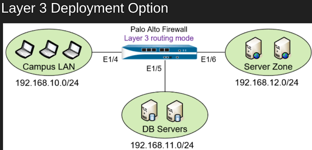
Layer 3
In a Layer 3 deployment, the firewall routes traffic between multiple ports using TCP/IP addressing. Before you can configure Layer 3 interface, you must configure the virtual routers that you want the firewall to use to route the traffic for each layer 3 interface.
layer 3 deployments require more network planning and configuration preparation than do most other firewall interfaces but still are the most widely used in firewall deployments.
Labels: Palo Alto modes and types


0 Comments:
Post a Comment
Subscribe to Post Comments [Atom]
<< Home