Sunday, July 13, 2025

How to configure Dynamic Routing protocols in palo Alto Firewall(BGP and OSPF )

 BGP vs2 OSPF:


Configure Interfaces

  • Go to Network > Interfaces.

  • Select the interface (e.g., ethernet1/1, ethernet 1/2, ethernet 1/3) and assign it to the correct virtual router and zone.

  • Enable Layer 3 mode and assign an IP.

Configure OSPF (Open Shortest Path First)

  1. Go to Network > Virtual Routers > [your VR] > OSPF.

  2. Enable OSPF by checking Enable OSPF.

  3. Set Router ID (can use interface IP).

  4. Configure Areas:

DMZ Router 1: Configuration

DMZ_R4(config)#router ospf 10
DMZ_R4(config-router)#net 172.16.16.4 0.0.0.0 area 0

Now Configure EIGRP
DMZ_R4(config)#router eigrp 6
DMZ_R4(config-router)#network 3.3.3.3 0.0.0.0
DMZ_R4(config-router)#no auto-summary

Redistribute the EIGRP Into OSPF
DMZ_R4(config)#router ospf 10
DMZ_R4(config-router)#redistribute eigrp 6 subnets

DMZ Router 2 Configuration
DMZ-R5(config)#router ospf 10
DMZ_R5(config-router)#net 172.16.16.5 0.0.0.0 area 0
DMZ_R5(config-router)#net 4.4.4.4 0.0.0.0 area 1

4. Configure BGP (Border Gateway Protocol)

  1. Go to Network > Virtual Routers > [your VR] > BGP.

  2. Enable BGP and set:

    • Local Autonomous System (AS) number

    • Router ID

  3. Configure Peers:

    • Add BGP Peer (e.g., neighbor IP, remote AS).

Trust Router BGP Configurations
Trust_r1(config)#router bgp 100
Trust_r1(config-router)#neighbor 10.1.1.254 remote-as 300

Trust_r1(config-router)#network 1.1.1.0 mask 255.255.255.0


OSPF Configuration On Palo Alto:


BGP Configurations on Palo Alto:


CLI Command:
> show routing route
> show routing protocol ospf neighbor
> show routing protocol bgp summary

BGP(Boarder Gateway Routing protocol)

BGP(Boarder Gateway Routing protocol)

It is an EGP Protocol (it can form neighborship between two different AS's)

It is a Path Vector routing Protocol (it uses multiple attributes to select best path)

It is highly scalable than IGP (it can have lakhs of routes in its BGP table)

It is reliable protocol (it uses TCP)

It uses TCP port number 179 before establish neighborship it have to form TCP connection (three way hand shake process).

only BGP is fully reliable routing protocol.

It is more secure than any other routing protocol because all message will travel on TCP protocol

It is a classless routing protocol

It support manual summarization

Administrative Distance: IBGP 200, EBGP 20.

A.S. size is 2bytes(0-65535) and 4bytes(0.0-65535.65535).

Public A.S= 1 to 64511, Private AS=64512 to 65534.

BGP doesn't support dynamic neighbor discovery.

it supports only md5 authentication

BGP convergence is slow as compare to IGP.

Note:we can't configure more than one AS on a single router.

Note:BGP sends all type of packets as unicast

AS (Autonomous System):

In the world of BGP, each routing domain is known as an Autonomous System, or AS.

Like IP addresses, Autonomous System Numbers have to be unique on the Internet.

An AS is a collection of networks under a single administrative domain.

The Internet is nothing more but a bunch of AS that are connected to each other.

Within an Autonomous System, use an IGP like OSPF, RIP, ISIS or EIGRP.

Between different Autonomous Systems, use an External Gateway Protocol.

BGP uses the Autonomous System (AS) number for its loop prevention mechanism.

Autonomous System numbers are 16-Bit or 2-Octed Autonomous System numbers.


BGP Flavors:

There are two flavors of BGP Internal BGP and External BGP.

IBGP (Interior Border Gateway Protocol):

  •  If the peers are in the same AS called Internal BGP (iBGP).
  •  Internal BGP (IBGP) is between the same Autonomous System Number.
  • Routes learned from IBGP peer will not be advertised to other IBGP peers.
  • By default, Internal BGP (IBGP) peers are set with TTL value = 255
  • Internal BGP (IBGP) routes have an Administrative Distance of 200.
  • Next hop remains unchanged when route is advertised to IBGP peer.
  • Internal BGP (IBGP) peers do not need to be directly connected.

EBGP (Exterior Border Gateway Protocol):

  •  If peers are in a different AS called external BGP (eBGP).
  •  EBGP is peering between two different Autonomous System (AS).
  •  Routes learned from eBGP peer will be advertised to other peers.
  •  EBGP peers are set with TTL = 1, means neighbors directly connected.
  •  External BGP (EBGP) routes have Administrative Distance of 20.
  • Next hop changed when it is advertised to EBGP peer by default.
  • External BGP (EBGP) the neighbors need to be connected directly.

Types of Messages in BGP:

For communication with the peer/NBR BGP uses the 5th type of message which has been

demonstrated below.

1. Open message

2. Keep-alive message

3. Update message

4. Notification message

5. Route-refresh message

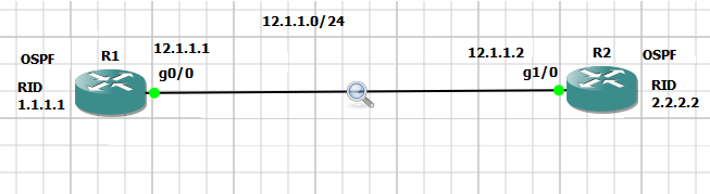
Now I’m using one simple topology to understand BGP’s message


1. Open message –

The OPEN message is used to establish a BGP adjacency. Or you can say that--

➢This is the first message of BGP Protocol

➢Once TCP connection / Three way handshake process is established then open message will be

sent, open message does not send periodically with the NBR.

➢Open message is exchanged by the BGP to exchange initial configuration with neighbors (NBR)

such as –

1. Message type

2. BGP version

3. Own AS (autonomous number)

4. Hold down timer -180sec

5. BGP identifier (Router-id)

So far we have discussed about open message’s theory, now it’s time to prove it that it is happing same

what we have discussed, I have illustrated a screenshot to understand a little bit using simple packet

Capture


2. Keep-alive message.


1. Keep –alive messages are sent periodically after every 60sec.
2. It is used to inform to the neighbor that still I’m alive, If any router does not receive
keep-alive message within hold down timer 180sec then it will assume that neighbor
may be down or something else issue then it will immediately break the neighbor-ship
with the its NBR.
3. Keep-alive message’s type code is –4.

3. Update message –

1. It is used to exchange prefix information/Network information with its neighbors.
2. Or you can say that Update packets will be responsible to carry routes information.
There are some field contains in updates message –
A. Path Attributes: Some criteria used by selection of best path.
B. Prefix info/NLRI: Network layer reach -ability information.
C. Withdrawn routes: The prefix that goes down.

Note –Still, I didn’t advertised prefix (192.168.1.0/28) using BGP network command, let’s
advertised what happens once we advertise it.

The moment you advertise prefix 192.168.1.0/28 using bgp command #network
192.168.1.0 mask 255.255.255.240 then BGP will send immediately update message
towards its neighbor.

Now we will check what information will be contain in update message –

4. Notification Message:

1. A BGP notification message is sent when an error condition is detected.
2. Notification messages include an error code, an error sub code, and data related to the error.
1. Notification message will be sent, in case of error detection and this message would inform its
neighbor case of problem.
Now lets see notification message just putting wrong as on R2 router –
R2(config-router)#neighbor 10.1.1.1 remote-as 100


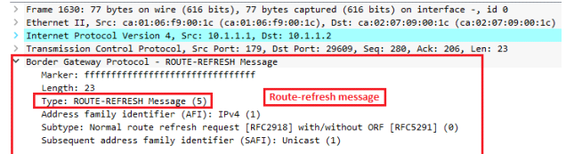
5: Route-refresh message –
1. Route refresh capability is the most preferred method…when you change your BGP
policy you just send a message to your BGP neighbor and it will re-send you all its
prefixes, there will be no disruption at all.
2. Whenever you will change BGP policy/configuration, you might be run the command -
clear ip bgp * soft in/out at that time you can check route-refresh message.
3. A soft reset allows the application of a new or changed policy without clearing an active
BGP session. The route-refresh feature allows a soft reset to occur on a per-neighbor
basis and does not require reconfiguration or extra memory. A dynamic inbound soft
reset generates inbound updates from a neighbor.


Recommendation for you-# clear ip bgp * soft in/out this command can be harmful for

your organization if you network is live, make sure you know the meaning of this command

then use it.


FSM(finite state mechnism) of BGP / BGP neighborship states
1 Idle:neighbor shutdown / waiting for start 3-way handshake.
2 Connect:try to form TCP connection, but wan't be confirmed
3 Active:TCP connection not completed, retrying to form tcp connection
4 Open-sent:TCP connection completed and sent open msg.
5 Open-confirm:exchanged open msg, perameter agreed, send keep-alive after 60sec
6 Established:peering completed, update is exhanged.


BGP Path Selection:
IGPs, such as EIGRP or OSPF, choose routes based on lowest metric. They attempt to find the shortest, fastest way to get traffic to its destination. BGP, however, has a different way of route selection. It assigns various attributes to each path; these attributes can be administratively manipulated to control the path that is selected.
• RIP selects the path with the lowest hop count.
• OSPF selects the path with the lowest cost.
• EIGRP selects the path with the highest bandwidth and lowest delay (unless you change the K values)
• BGP –best path depends on the attributes.
BGP selects the best path based on a list of attributes.
Point to be noted


Path attributes –
Path attributes is one kind of criteria which is used for best path selection in bgp.
BGP chooses a route to a network based on the attributes of its path. Four categories of attributes exist as follows:
Well-known mandatory –
Must be recognized by all BGP routers, present in all BGP updates, and passed on to other BGP routers. Such as -Next hop AS path, origin code. 
Well-known discretionary –
Must be recognized by all BGP routers and passed on to other BGP routers but need not be present in an update, such as -local preference. 
Optional transitive –
Might or might not be recognized by a BGP router but is passed on to other BGP routers. If not recognized, it is marked as partial, such as Aggregator, community.
Optional nontransitive –
Might or might not be recognized by a BGP router and is not passed on to other routers, for such as -Multi-Exit Discriminator (MED), originator ID. Best path selection attributes in BGP

Saturday, February 22, 2025

HSRP(Hot Standby Router Protocol)

 First Hop Redundancy Protocol (HSRP)–

1. HSRP stands for – Hot standby router protocol.

2. It is a Cisco proprietary protocol.

3. It is used to provide redundandancy in the network, Suppose If we have two links primary & secondary link and In case of primary link goes down then secondary link will take over and all the traffic will go through via secondary link.

OR

4. It’s aggregate two or more physical gateway into a single virtual gateway.

5. Hello timer-3sec , Hold down timer -10sec (by default)

6. It uses multicast address to send hello message -224.0.0.2 and for HSRP version 2 – 224.0.0.102

7. By default priority – 100 but you can change up to 255.

8. HSRP uses UDP port number – 1985

9. It uses multicast mac–address – 0000:0607.acXX Where XX represents group number, what you assigned on the router while configuring group no.

10. By default group no -0 but you can change it up to 255.

11. Supports plain text, MD5 authentication.

12. By default preempt is disabled for active router and preempt command works when you configure it on the router.

13. By default built in track command is enabled.

14. By default in priority is decrement – 10 Note 1 – For one group only one device can be active and one device can be standby, remaining device would be listening state.

HSRP election process (Bydefault)–

1. Priority

2. Highest active physical interface IP address.


Note 2 - If you enable HSRP within 10sec (Hold down timer) then election would be on the basis of physical IP address, as you know that by default priority is 100 in HSRP and if you have changed priority and also enabled preempt then election will be done on the basis of priority and that router’s priority will be higher become active, second highest priority– standby.

HSRP States –

There are six states in HSRP.

1. Disabled state

2. Init state (initialization

3. Speak state

4. Listen state

5. Standby state

6. Active state

Disabled state –

This is the state of a device that is not yet ready or able to participate in HSRP

Init state –

This is the first state when HSRP starts. You’ll see this when HSRP just got enabled on the interface.

Listen state –

The router knows the virtual IP address and will listen for hello messages from other HSRP routers.

Speak state –

The router will send hello messages and will join the election to see which router will become active or standby.

Standby –

The router didn’t become the active router but will keep sending hello messages. If the active router fails it will take over.

Active –

The router will send hello messages and will join the election to see which router will become active or standby. 

Let’s understand few scenarios in HSRP –


Condition 1- If priority by default is 100 and we enable HSRP on every router (R1,R2,R3) within 10sec then R3 router will become Active router as on R3 IP address is highest IP address, and second highest IP address will become standby (R2) and R3 would be listing state. Let’s prove it.

I have just enabled HSRP within 10sec on every router, didn’t change priority of router then got output and you do delay while configuring then that router would be active router on which you enabled HSRP first.

• RTR(config)#interface gigabitEthernet 1/0

RTR(config-if)#standby 1 ip 192.168.1.100


Condition-2:

 If you have changed priority on every router then that router would be active of which priority is high than other router and second highest priority would be standby (R2). And In my scenario I have taken 50mbps link from ISP then we have to utilize the link accordingly.


Condition – 3
If you have seen two things above now there are one condition here If you change the priority of R3 router and want to make active router it, then It will not become active router unless/until R1 router goes down. Till then R3 will not become active router. And R3 router can only give the challenge to R2 router as R2’s priority less than R3 router, here I’m going to change priority of R3 router which I have changed – 150 and R3 router is giving to challenge R2 router because R2 router ‘s priority 120. Hence R3 router will become standby state, R2 would be listen state and still you will see that R1 router is in Active state. Let’ prove it.

• (config)#interface gigabitEthernet 3/0
• RTR(config-if)#standby 1 priority 150


Point to be noted – why R3 router didn’t get active router – Still I didn’t enabled preempt on every router, one more thing we want to know preempt works when we have configure priority on every router. 

Condition-4:

Now I’m going to enabled Preempt on every router and this command will push to every router that my router’s priority is higher than you therefore I will become active router and second router’s priority will be come standby router, other would be listing state. Let’s verify it.

• Airtel_RTR(config)#interface gigabitEthernet 1/0
• Airtel_RTR(config-if)#standby 1 preempt


As you can see that preemption is enabled on every router and If you want to change priority of any router lets assumed you changed the priority and you want that router will become active router, till then that router would not become active router unless active router goes down. Once you enabled preemption then election will be on behalf of priority.

Now I’m going to show full topology and with discuss it – whatever I have written in the binning.

Here I have taken screenshot to show you only one router –


HSRP  Topology:


How to enable HSRP –

RTR(config-if)#interface gigabitEthernet 1/0
RTR(config-if)#standby 1 ip 192.168.1.100

How to change priority – ( 0-255)

RTR(config-if)#interface gigabitEthernet 1/0
RTR(config-if)#standby 1 priority 130 How to enable preempt command –
RTR(config-if)#interface gigabitEthernet 1/0
RTR(config-if)#standby 1 preempt

Below the command what I did up to here –


Output of HSRP:


Let’s check it - It is reachable from LAN PC.


Let’s assume that If WAN link goes down then what will you do – All traffic will come at Airtel_RTR, Just simply will be drop as at that time on Airtel router - will be active state. Then we need to enable track command on the router.


Saturday, April 20, 2024

Palo Alto ‘mode’ configurations

 What are the four deployment mode, and explain?

a.TAP Mode providing:

 A Network tap is a device that provides a way to access data flowing across a computer network.

Tap mode deployment allows you to passively monitor traffic flows across a network by way of a switch SPAN or mirror port.

The SPAN or mirror port permits the copying of traffic from other ports on the switch. By dedicating an interface on the firewall as a TAP mode interface and connecting it with a switch SPAN port, The Switch SPAN port provides the firewall with the mirrored traffic.


Why use Tap Mode?

By deploying the firewall in TAP mode, you can get visibility into what applications are running and your network
without having to make any changes to your network design.

In addition, when tap mode, the firewall can also identify threats on your network.

Keep in mind, however, that because the traffic is not running through the firewall when in tap mode it can not take any action on the traffic, such as blocking traffic with threats or applying QoS traffic control.

b.V-Wire Mode /Virtual Wire mode:

In a virtual wire deployment, you install a firewall transparently on a network segment by binding two

firewall ports(Interfaces) together. The virtual wire logically connects the two interfaces, hence,

the virtual wire is internal to the firewall.


Use a virtual wire deployment only when you want to integrate a firewall into a topology seamlessly. Two connected interfaces on the firewall need not do any switching and routing.

the firewall is considered a bump in the wire for these two interfaces.


How does it work in Virtual wire mode?

Each virtual wire interface is directly connected to a layer2 or layer3 networking device or host.
The virtual wire interfaces have no layer2 or layer3 address.
When one of the virtual wire interfaces receives a frame or packet, it ignores any layer2 or layer3 address
for switching or routing purposes but applies your security or NAT policy rule before passing an all frame
or packet over the virtual wire to the second interface and on to the network device connected to it.
virtual wire interface will allow layer2 and layer3 packets from connected devices to pass transparently as 
long as the policies applied to the zone or interface allow the traffic. The virtual wire interfaces themselves
don't participate in routing or switching.

L 2 Interface
In a layer 2 deployment, the firewall provides the switching between two or more Networks.

Devices are connected to a Layer 2 segment;
The firewall forwards the frames to the proper port, which is associated with the MAC address identified in the frame. Configure a layer 2 interface when a switch is required.


Layer 2

You can either configure a L2 with no VLANs or with VLANs.
when your organization wants to divide a LAN into separate Virtual LANs(VLANs)to keep traffic and policies for different departments separate, you can logically group layer 2 hosts into VLANs and thus divide a Layer 2 Network segament into broadcast domains.
For example, you can create VLANs for the finance and Engineering departments. To do so, configure a layer 2 interface, subinterface, and VLAN.


Layer 3

In a Layer 3 deployment, the firewall routes traffic between multiple ports using TCP/IP addressing. Before you can configure Layer 3 interface, you must configure the virtual routers that you want the firewall to use to route the traffic for each layer 3 interface.

layer 3 deployments require more network planning and configuration preparation than do most other firewall interfaces but still are the most widely used in firewall deployments.


Friday, April 19, 2024

Palo Alto Next-Generations firewall

What Makes Palo Alto Different?

Based on patent-pending App-ID™ technology, Palo Alto Networks' next-generation

firewalls accurately identify applications - regardless of port, protocol, evasive tactic

or SSL encryption - and scan content to stop threats and prevent data leakage.

Enterprises can for the first time embrace Web 2.0 and maintain complete visibility

and control, while significantly reducing the total cost of ownership through device consolidation.

Here are some of the unique capabilities available only in next-generation firewalls from Palo Alto Networks.

* The only firewall to classify traffic based on the accurate identification of the

application, not just port/protocol information.

* The only firewall to identify, control and inspect SSL encrypted traffic and

applications.

* The only firewall with real-time (line-rate, low latency) content scanning to protect

against viruses, spyware, data leakage and application vulnerabilities based on a

stream-based threat prevention engine.

* The only firewall to provide graphical visualization of applications on the network

with detailed user, group and network-level data categorized by sessions, bytes,

ports, threats and time.

* The only firewall with line-rate, low-latency performance for all services, even under load.

App-ID:  classifying traffic on all ports all the time – irrespective of protocol, encryption, and/or any other evasion tactic Accurate traffic classification is the heart of any firewall, with the result becoming the basis of the security policy. Traditional firewalls classify traffic by port and protocol, which, at one point, was a satisfactory mechanism for securing the perimeter. 
Today, applications can easily bypass a port-based firewall; hopping ports, using SSL and SSH, sneaking across port 80, or using non-standard ports. App-IDTM, a patent-pending traffic classification mechanism that is unique to Palo Alto Networks, addresses the traffic classification limitations that plague traditional firewalls by applying multiple classification mechanisms to the traffic stream, as soon as the device sees it, to determine the exact identity of applications traversing the network.


App-ID:
Classify traffic based on applications, not ports. App-ID uses multiple identification mechanisms to determine the exact identity of applications traversing the network. The identification mechanisms are applied in the following manner:
• Traffic is first classified based on the IP address and port.
• Signatures are then applied to the allowed traffic to identify the application based on unique application properties and related transaction characteristics.
• If App-ID determines that encryption (SSL or SSH) is in use and a decryption policy is in place, the application is decrypted and application signatures are applied again on the decrypted flow.
• Decoders for known protocols are then used to apply additional context-based signatures to detect other applications that may be tunneling inside of the protocol (e.g., Yahoo! Instant Messenger used across HTTP).
• For applications that are particularly evasive and cannot be identified through advanced signature and protocol analysis, heuristics or behavioral analysis may be used to determine the identity of the application. As the applications are identified by the successive mechanisms, the policy check determines how to treat the applications and associated functions: block them, or allow them and scan for threats, inspect for unauthorized file transfer and data patterns, or shape using QoS.

User-ID: securely enable applications on your network based on users and groups – not just IP addresses

Traditionally, security policies were applied based on IP addresses, but the increasingly dynamic nature of users and applications means that IP addresses alone have become ineffective as a mechanism for monitoring and controlling user activity. Palo Alto Networks' next-generation firewalls integrate with the widest range of user repositories on the firewall market, enabling organizations to incorporate user and group information into their security policies. Through User-ID, organizations also get full visibility into user activity on the network as well as user-based.

Content-ID: Real-time content scanning blocks threats, controls web surfing, and limits data and file transfers.

Content-ID combines a real-time threat prevention engine with a comprehensive URL database and elements of application identification to limit unauthorized data and file transfers, detect and block a wide range of threats and control non-work related web surfing. The application visibility and control delivered by App-ID, combined with the content inspection enabled by Content-ID means that IT departments can regain control over application traffic and the related content. The NSS-rated IPS blocks known and unknown vulnerability exploits, buffer overflows, DoS attacks, and port scans from compromising and damaging enterprise information resources. IPS mechanisms include: Protocol decoder-based analysis statefully decodes the protocol, Protocol anomaly-based protection detect non-RFC compliance protocol usage, Stateful pattern matching detects attacks over multiple packets, Statistical anomaly detection prevent rate-based DoS floods, Heuristic-based analysis detect anomalous packet and traffic patterns such as port scans and port sweeps, Custom vulnerability or spyware phone home signatures that can be used in either the anti-spyware or vulnerability protection profiles, Other attack protection capabilities such as blocking invalid or malformed packets, IP defragmentation, and TCP reassembly to protect against evasion and obfuscation methods.

URL Filtering by Bright Cloud:
Complementing the threat prevention and application control capabilities is a fully integrated, URL filtering database consisting of 20 million URLs across 76 categories that enables IT departments to monitor and control employee web surfing activities.

  • File and Data Filtering:
Data filtering features enable administrators to implement policies that will reduce the risks associated with the transfer of unauthorized files and data. 
  • File blocking by type: 
Control the flow of a wide range of file types by looking deep within the payload to identify the file type (as opposed to looking only at the file extension).
  • Data filtering: 
Control the transfer of sensitive data patterns such as credit card and social security numbers in application content or attachments. 

  • File transfer function control: 
Control the file transfer functionality within an individual application, allowing application use yet preventing undesired inbound or outbound file transfer.

Saturday, August 6, 2022

OSPF(Open shortest path first)

OSPF stands for open shortest path first.

1. It is an open standard protocol. Open standard means that It supports two different vendors like – Cisco, Huawei, juniper, etc.

3. It is a link-state routing protocol. link-state means In OSPF routers do not send periodically update, only send update whenever changes will occur in the topology and that information will be sent partial means in which changes occurred.

And link state routing protocol whenever share own prefix information that time it also shares own subnet mask information with its neighbors.

4. It is an IGP protocol. IGP means it works within AS.

5. OSPF uses the SPF algorithm or you can say the Dijkstra algorithm for best path selection.

6. Supports unlimited hop count which means no limitation of hop count in OSPF.

7. OSPF uses protocol no – 89

8. It is a layer-3 protocol

9. AD value is = 110

10. Hello and dead interval timer = 10 sec, 40 sec (by default).

Broadcast and point to point = 10sec, 40sec.

Non- broadcast and point to multipoint = 30sec, 120sec.

11. Metric = Cost.

By default reference bandwidth = 100

Ethernet cost = 10

Fast Ethernet cost = 1

Giga ethernet cost = 1

Serial link cost = 64

Note – OSPF does not consider decimal values while calculating cost.

12. It is a classless routing protocol; classless means whenever it will share prefix information/ Network information with its neighbors that time it shares subnet mask information with the neighbors.

13. OSPF uses two multicast addresses-

224.0.0.5 (All routers listen)

224.0.0.6 (DR routers listen)

In OSPF hello packets are sent through multicast address 224.0.0.0.5

Note – In static case may be sent = 224.0.0.6

14. In OSPF must have one area called area 0 and all the areas must be connected to area 0.

15. Supports authentication.

Type 0 – Null authentication

Type 1 – Plain text authentication

Type2 – MD5 authentication

16. Incremental and triggered updates.

17. Introduce the concept of areas to ease management & control traffic.

18. OSPF provides a Hierarchical Network design with multiple different areas.

19. Routers send only changes in updates and not the entire routing table in periodic updates.

20. By default auto-summary is disabled

21. By default maximum path = 4 (Maximum up to 16).

How to calculate OSPF cost = ( In serial link )


  1. Types of table in OSPF -

OSPF maintains three routing tables –
1. Neighbor table
2. Database table
3. Routing table
Neighbor table –
The neighbor table contains information about the directly connected OSPF neighbors forming adjacency (Keeps directly connected Nbrs.) See the below snapshot for reference purposes-


# show ip ospf neighbor

2. Database table-

The database table contains information about the entire view of the topology with respect to each other (Complete information on the same area but no information on the other area).

#show ip ospf database


3: Routing table –

Routing table contains information about the best path calculated by SPF algorithm in data base table.

#show ip route ospf


Points to be noted –

In ospf each router makes own database table and in that database table are LSA and in that LSA router Keeps Links information.

For an instance – R1 router.


Types of the packet in OSPF:

 Type1 :hello

 Type2 : DBD database description

 Type3: LSR Link state request

Type4: LSU Link state update (retransmission time out 5sec)

Type5: LS Ack link state acknowledge


Hello:-

1. Hello packets are used to establish & maintain Neighbor-ship.

2. Hello packets are used to discover neighbor-ship.

3. Keep alive.

4. Periodically send after every 10sec/30sec (Brod, P2P/Non-Broadcast).

5. Dead timer 40sec/120sec (Brod, P2P/Non-Broadcast).

6. Hello messages are sent through multicast address – 224.0.0.5.

7. In static neighbor-ship hello messages/packets are sent unicast.

Hello packets content:-

1. OSPF version

2. Message type

3. Packet length

4. Router-id

5. Area-id

6. Checksum value

7. Authentication type

8. Authentication data

9. Subnet mask

10. Hello & Dead interval timer

11. Priority

12. DR & BDR IP address

13. Stub area flag.

 Type2 : DBD database description.

1. In this packet routers only exchange empty DBDs packets with their own sequence number to neighbors.

2. Also routers share MTU size in this packet. (MTU Size must be the same in a packet of the router’s interface).

3. Master/ Slave is elected. And that router will become the master router whose router-id will be higher than the other and the master router will start the exchange of information and other routers (Slave) will give a response to the master.

Type-3– Link state Request (LSR):-

In this state will request to its neighbors that I am having some LSA header and I need complete information about that ok let me check in my database table, and Vice versa.

Type-4 – Link state update (LSU):-

In this packet/message router will share updates about its own links information to neighbors.

Type -5- link state acknowledgment (LSack)

Then routers will give each other an acknowledgment message.


Types of OSPF states

1. Downstate

2. Init state

3. 2-way state

4. Ex-start state

5. Exchange state

6. Loading state

7. Full state


Down state-
This is the first state of OSPF, this state indicates the no information has been received from its neighbor Means Hello packet still did not received from its neighbor.


Then router move next state.

2. Init state-
This state designates that hello packet received from its neighbor.


How to configure Dynamic Routing protocols in palo Alto Firewall(BGP and OSPF )

 BGP vs2 OSPF: Configure Interfaces Go to Network > Interfaces . Select the interface (e.g., ethernet1/1, ethernet 1/2, ethernet 1/...